
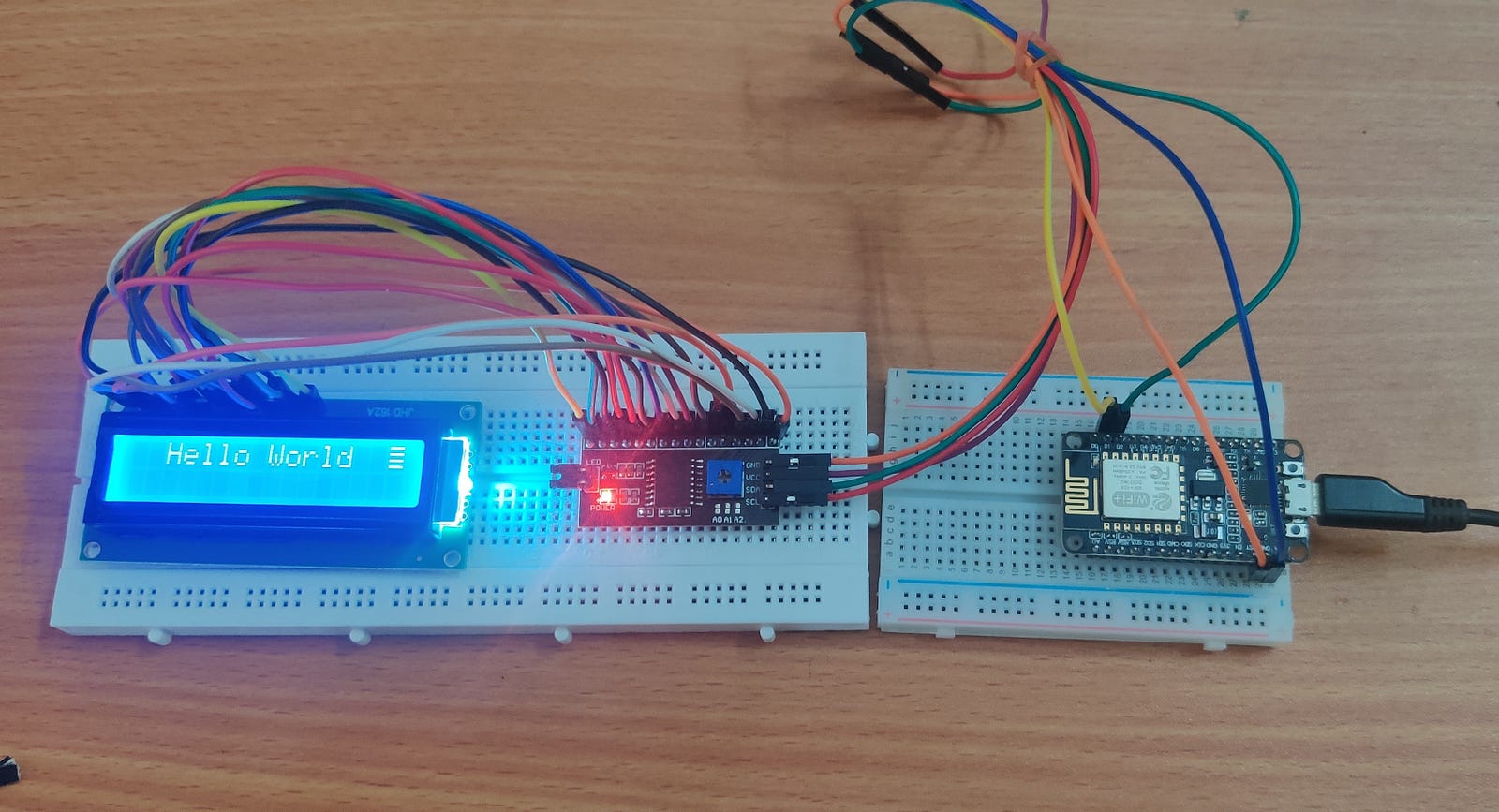
This tutorial will guide you to interface LCD_I2C with esp8266 nodeMCU. Here we will use LCD I2C to communicate with esp8266 NodeMCU because it only requires 2 wires.
I2C Protocol
Inter-Integrated Circuit or I2C is a multi-controller/multi-target serial communication bus. Uses to attach lower-speed peripheral ICs to processors and microcontrollers in small-distance or intra-board communication.
It has two lines: Serial Data line (SDA) and Serial Clock line (SCL). The typical voltage it requires is +5 V or +3.3 V.
Serial Data Line (SDA): It is a half-duplex line, which sends data from the master to the slave or vice-versa.
Serial Clock Line (SCL): Serial clock is primarily controlled by the master.
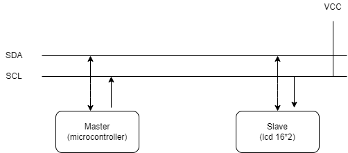
The message format for SDA and SCL lines
START and STOP condition:
All transactions in SDA and SCL begin with START (S) and are terminated with STOP(P). A High to LOW in the SDA line while HIGH in SCL defines the START condition. A LOW to HIGH in the SDA line, while SCL is HIGH, describes a STOP condition.

Repeated START condition:
Between each START and STOP condition, the bus is considered as busy. If the master wants to transfer data without releasing the bus, it issues START without STOP, called REPEATED START.
Target Address:
After the START condition, the target address is sent in data format. It is 7-bit long.
Read/Write Bit:
Eight-bit is the data direction(R/W) bit. If it is 0, then it indicates a transmission(WRITE). if it is 1, then it indicates as request data(READ).
ACK/NACK Bit:
After every successful data received target sends the ACK bit to the controller.
LCD 16X2 and PCF8574
Liquid crystal display (LCD) comes in different sizes. LCD 16x2 has 16 columns and 2 rows. It can show a max of 32 characters. In LCD 16x2 each column starts from 0 to 15, and the row starts from 0 to 1. To write a character at a specific location in LCD, we require a specific column and row location. For example
LCD.println(0, 1)
To direct connect LCD with MCU, we need to secure all these pins to MCU. But we can simplify these connections using PCF8574. The PCF8574 module provides general-purpose remote I/O expansion for most microcontroller families using the I2C interface.
Circuit Diagram
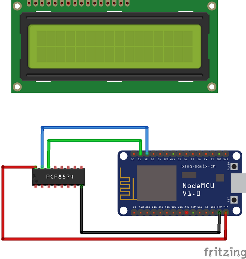
As shown in the schematic diagram, LCD I2C is connected with esp8266 with pins described in the below table.
Component Required
- Esp8266
- LCD and PCF8574 I2C
- Breadboard
- Connecting Wires
Setup for LCD I2C in Arduino IDE
If the LCD I2C module is not set up, then we need to download the library-related LCD I2C module. In Arduino, go to the following location:
Sketch -> Include Library ->Manage Library ->search liquid crystal i2c.
if esp8266 node-12e is not available to download on board then do this:
Copy the following link:
http://arduino.esp8266.com/stable/package_esp8266com_index.json
And add it in the following place:
File->Preferences ->Addition Boards Manager URLs-> add link there
Coding
To write text in LCD, we need to address it. can be calculated with the following code snippet below: